HackLive’s Hardware Challenge
May 07, 2021
 This year’s Kernelcon was a bit different. Both as organizers and as conference attendees, our group was a bit fatigued on virtual conferences and we wanted to do something fresh. We workshopped some ideas and ultimately landed on an idea we called HackLive. In short, the core of HackLive was to create a one-to-many job shadow scenario where attendees could watch and learn from an expert working on a challenge in real time. To try and make it more engaging, we added a voting component. @ScotchSec and I developed the Hacker Hotkey (still some available), which would help facilitate voting and serve as a general purpose, fully customizable macro pad after the conference. Normally, that’s the end of my hardware shenanigans for Kernelcon. However, HackLive was setup to have a hardware challenge to be solved by Kingpin (Joe Grand). And through a series of circumstances, I ended up taking on the task. This blog post will cover what went into building the HackLive challenge and what came out the other side!
What Went In
I did not want to build a CTF challenge. I didn’t want it to be difficult or esoteric. Instead, I wanted to build a challenge that would cover the essential skills that I thought a hardware hacker should know. At that point, it made logical sense to built the challenge in reverse. Build a list of skills, and then create scenarios where those skills would be used. So I made the following list based upon personnel experience, research, and formal training from, poetically, Joe Grand:
- Soldering
- Identifying parts
- Identifying dev ports (UART, JTAG, etc)
- Tracing connections
- Tapping signals
- Analyzing signals
- Injecting own signals
- Defeating anti-RE (epoxy, case switches, etc)
- Reading datasheets and schematics
Now I had a list of skills, but then ran into the crux of building a hardware challenge such as this. How can I create a challenge to force the usage of these skills? Even if I made something that had an intended path that covered all the skills, with physical access, there is many many ways to attack a problem. Some of which are, more than likely, far easier than my intended path, which by nature has many steps. An additional problem was I can’t hide things in server-side code or encrypted areas, everything I made would be entirely exposed. Ignoring the exposure issue for a moment, I was able to come up with some contrived scenarios where a skill or two could be tested at a time, but how could I chain a series of those scenarios together? I needed a story to glue everything together with…

As a general lover of space, the idea of a broken space ship quickly came to mind. Not only could I build a fun narrative around it, but it can easily be structured into modules, such as fuel system, power system, communications system, and etc. And those modules could be chained together into some sort of master system that monitors the status of everything. I found the glue! (This glue bled out from my challenge and all of HackLive was eventually themed around space. Talk about some strong glue!) Now back to the exposure problem.
The exposure problem is something skilled, incentivized, and well-funded embedded system organizations and engineers face and struggle to solve, so it’s improbable that a hobbyist such as myself is going to solve it overnight. However, my solution ended up being a simple one. Since this challenge is more or a less a game, I can create the rules. If I package my modules in such a way that things I want to be seen are seen, and everything else is inside a case, I can just make a rule that everything inside the case is out of bounds. I didn’t love this solution, but it would allow the challenge to be as succinct and educational as possible, which is the ultimate goal of HackLive and thus would be acceptable. With the hurdles out of the way, it was time to start prototyping and building!
What Came Out
 I’ll skip over all the prototyping/development and jump right into the finished challenge that got delivered to Joe Grand. The following context was read to Joe as he began the challenge:
You are one of the universe’s greatest hackers. You awake aboard a foreign spaceship on a desolate distant planet. Your best chance of survival is to leave the planet using the spaceship’s autonomous flight; however, the ship needs some work before the computer can launch it. You find several of the ship’s systems are destroyed. Luckily, it would seem fate is on your side. You found a box full of spare parts and systems. There was a note on the box that said “remember to check the logs”. You must get the spaceship working, your survival depends on it.
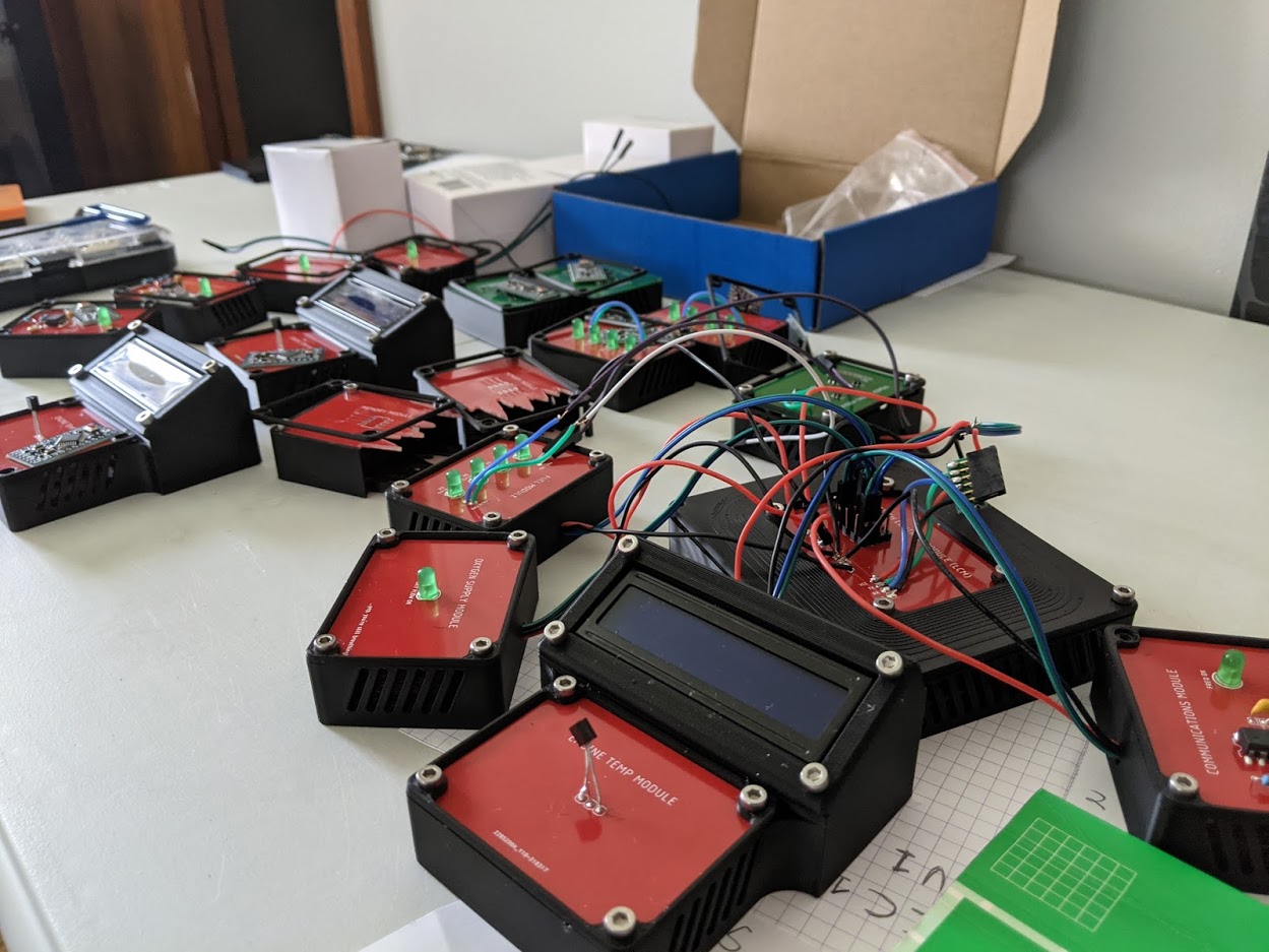
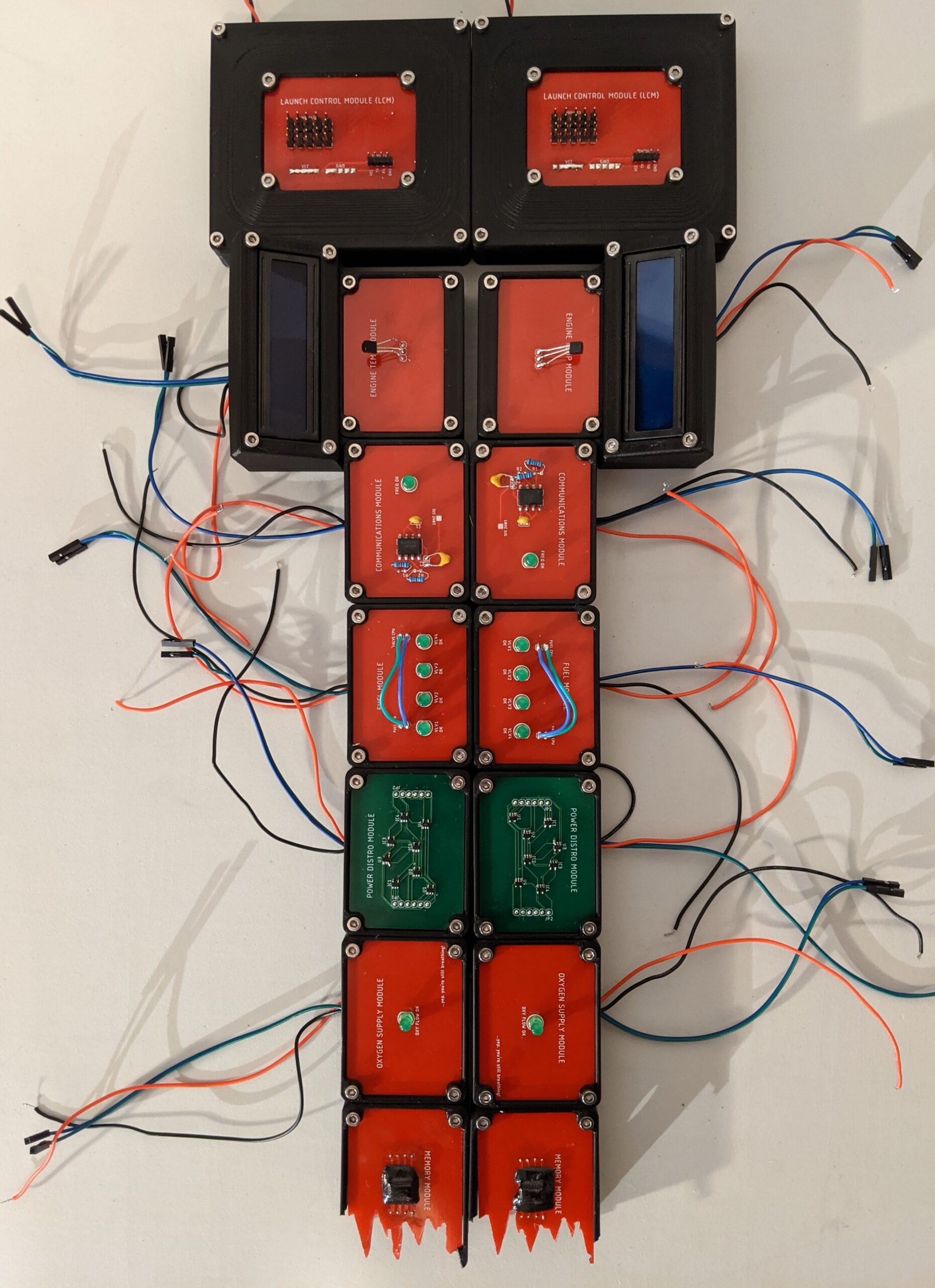
In total, the following 7 modules were created and found inside the aforementioned box:
- Launch Control Module (LCM)
- Engine Temperature Module
- Communications Module
- Fuel Module
- Power Distribution Module
- Oxygen Module
- Memory Module
Everything is 3.3v. Each module has 2 serial wires, power, and ground coming out of the case, except the LCM which only has power and ground. I designed 3d printed cases for everything, which had mounts for Arduino Pro Minis. Everything inside of the case was out of scope.
Launch Control Module (LCM)

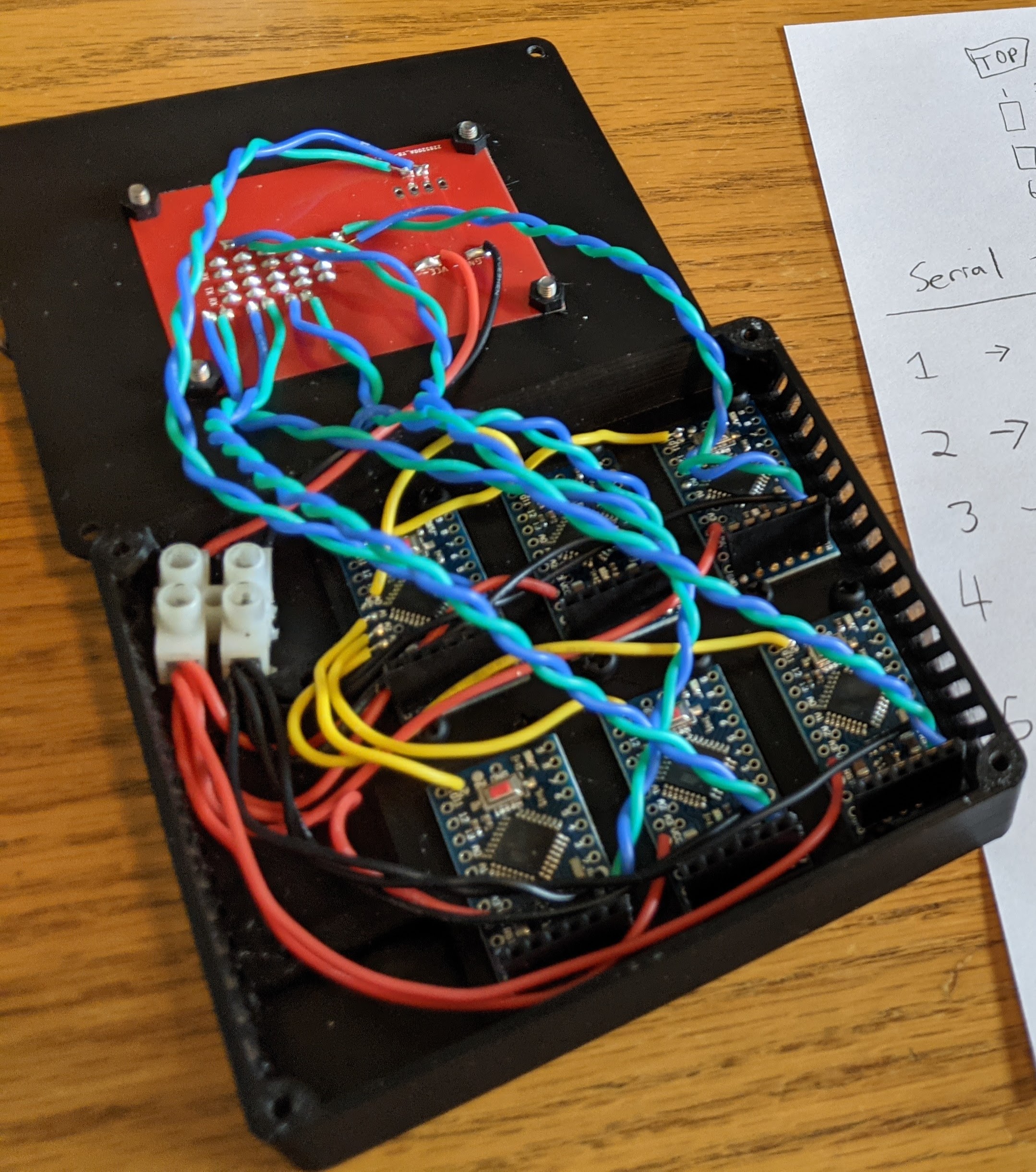
The LCM was the centralized computer. It was made up of 6 Arduino Pro Minis. One main Arduino managed the LCM’s console. This console provided status reports of the modules, logs of the modules, and is used to initiate a launch if all the conditions were correct. The logs for each module function as clues and each one can be seen in each module section below. The other 5 Arduinos manage an interface to be connected to a specific sub-module (temp,fuel,etc). They verify the status of a sub-module via a serial connection, which has a unique GUID signature. That way you cannot spoof the LCM into a launch-capable state, you must “solve” each module and get it into is “OK” state in order to launch. The LCM had 10 module ports; however, only 5 of them were active and had to be used for a specific module, so enumeration was required to determine what module had to be connected where.
Skills needed: Identifying dev ports, analyzing signals, soldering
Below is a sample of the LCM console: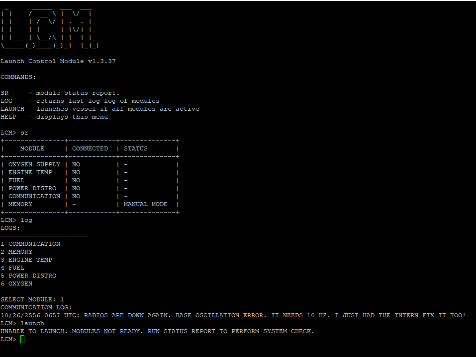
And a peek inside:
Engine Temperature Module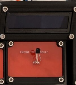

LOG: 10/26/2556 0657 UTC: ENGINES CAN’T PRIME WITHOUT THE PROPER HEAT. SOMETHING MIGHT BE WRONG IN SENSING CIRCUIT. THAT LAST WORMHOLE WAS FLIPPY!
The Engine Temperature Module has one Arduino Pro Mini. It reads the temperature using an exposed TMP36 sensor, which out of the box is wired incorrectly (GND and signal out are flipped). It also has a LCD display that shows the current temperature, target temperature, and a “Engine Primed. Status OK” message when the target temperature is reached. When this target temperature is reached, a “OK” message is sent to LCM, with the appropriate GUID signature. Until the wiring is corrected on the TMP36, the target temperature cannot be reached, no matter how much cooling or heating. The intended solve is to troubleshoot why the target temperature can’t be reached, lookup the datasheet for TMP36, find incorrect wiring, correct wiring by soldering, and then finally heat it to target temperature.
Skills needed: Identifying parts, reading datasheet and schematics, soldering, tracing connections
Communications Module

LOG: 10/26/2556 0657 UTC: RADIOS ARE DOWN AGAIN. BASE OSCILLATION ERROR. IT NEEDS 10 HZ. I JUST HAD THE INTERN FIX IT TOO!
The Communications Module has one Arduino Pro Mini. It reads the frequency in Hz that is created by a 555 timing circuit. The LCM log and silkscreen of the board call for a 10 Hz signal; however, the circuit is generating a 100 Hz signal. The intended solve is note it’s the wrong frequency, look up how a 555 timing circuit works, realize it has the wrong capacitor, and correct the capacitor by soldering. When the 555 circuit is generating a 100 Hz signal (+/- 10 Hz, cause the world isn’t perfect and neither are we), the Arduino will send “OK” message to the LCM, with the appropriate GUID signature.
Skills needed: Identifying parts, analyzing signals, reading datasheet, soldering
Fuel Module

LOG: 10/26/2556 0657 UTC: ONLY RECEIVING 1/4 THE FUEL WE SHOULD BE…HMMMMM
The Fuel Module has two Arduino Pro Minis, one Fuel CPU and one Valve CPU. The Fuel CPU is sending commands to the Valve CPU over serial via the exposed wires. It instructs the Valve CPU to open valves. There are 4 valve LEDs to indicate which valves are open. Out of the box, only the first valve is opening and therefore only one LED is lit. The intended solve is to tap the exposed serial wires between the Fuel and Valve CPUs, inspect the communication, note the Fuel CPU is only sending the command to open one valve, learn the syntax, and then inject messages to open the other valves so that all 4 valves are open. When the Arduino acting as the Valve CPU detects that all four valves are open, it sends “OK” message to the LCM, with the appropriate GUID signature.
Skills needed: Tapping signals, analyzing signals, injecting own signals, soldering
Power Distribution Module

LOG: 10/26/2556 0657 UTC: THIS CIRCUIT WAS DAMAGED BEYOND REPAIR, SO WE RECREATED THE BOARD FROM THE ORIGINAL SCHEMATIC (WHICH IS ATTACHED TO MODULE). WE HAD A GROUND ERROR AND FIXED IT, BUT IT DOESN’T WORK STILL, MAYBE WE DID SOMETHING WRONG?
The Power Distribution Module has one Arduino Pro Mini and comes with a schematic. The board has 4 AND gates and 4 OR gates connected in a random fashion, hence called the maze. The maze has 6 inputs and 6 outputs, also connected in a random fashion. The intended solve is to trace the maze and verify all the connections match the provided schematic. There are 3 differences between the maze and the schematic. 1 trace cut and 2 added jumpers are needed to correct it. The Arduino cycles through all 64 permutations of high/low on the 6 inputs and checks for a certain result on the 6 output pins for each permutation. Only when the corrections have been made to the maze will the checks be correct, at which point it sends “OK” message to the LCM, with the appropriate GUID signature. Note: I totally messed up this design and there were floating pins all over the place and I had to use some dirty software hacks to make it even remotely stable! Given more time, I would have made a revision. But things didn’t shake out that way!
Skills needed: Tracing connections, reading schematics, soldering
Oxygen Module

LOG: 10/26/2556 0657 UTC: NO ISSUES. THANK THE MAKER!
The Oxygen Module has one Arduino Pro Mini and has nothing needing to be solved. It is constantly sending the “OK” message to the LCM, with the appropriate GUID. Its purpose is to have a “known good” module for use in determining how to connect things to the LCM.
Skills needed: Identifying dev ports, analyzing signals
Memory Module
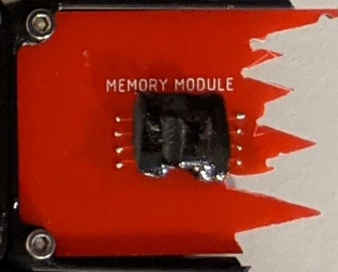
LOG: 10/26/2556 0657 UTC: MEMORY MODULE IS COMPLETELY DESTROYED. WE’LL NEED TO RECOVER DATA AND INPUT USING MANUAL MODE
The Memory Module has no Arduinos. It has a 24LC256 EEPROM covered with epoxy. The EEPROM has a launch code saved in memory. The intended solve is to scrape away the epoxy to determine what the part is, look up datasheet for connection information, solder on wires, and then recover the data using Arduino, programmer, or other tool.
Skills needed: Identifying parts, reading datasheet and schematics, defeating anti-RE, soldering
How to Launch
Once all the modules were in there “OK” state and correctly connected to the LCM, a launch command is initiated from the LCM console. After running the launch command, it would prompt for the launch code, which must be recovered from the memory module and manually entered. If the launch code is correct, a countdown will begin and then will end with a little ASCII art. Below is the moment Joe got the rocket to launch:
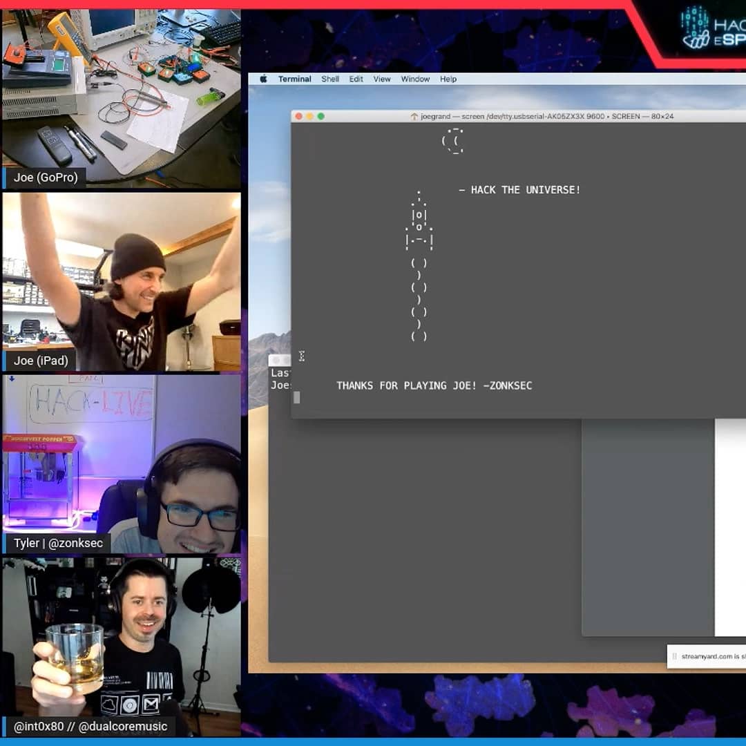
Here is the recording of Joe solving the challenge:
Materials
All the gerber files for the PCBs, 3d printed cases, and code can be found on my GitHub: https://github.com/ZonkSec/hardware-challenge-kernelcon-2021
Bonus Content: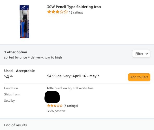
When we were first conceptualizing HackLive, we worried about being in a situation where a hacker was going too fast and would complete a challenge too early. So we came up with some hindrances the audience could vote to use to slow a hacker down. Ultimately, we were never in that situation, so they never happened. However, for a hardware challenge hindrance I bought the cheapest soldering iron I could find on Amazon. It was used and the ad read “little burnt on tip, still works fine”, as seen on the right. At one point late in the challenge, Joe needed a second soldering iron, so I had him open this terrible iron and we had a good laugh about it during and after.
Thanks for reading if you got this far! I hope you learned a little something. Special thanks to Joe Fitz who helped tabletop this challenge!